I want to dedicate this post to a very easy error to practice, mainly in the 1: 10,000 and 1: 1,000 maps used for cadastral purposes taken from the 1: 50,000 mesh.
Recall that in the previous post we saw how to generate this mesh, and previously we saw how go away until you get to a 1: 1,000 map. But the simplest mistake is to believe that this mesh can be split on the map, and this is not correct. The coordinate must be generated using latitude and longitude every time we want to create a denser mesh and if we do not see the result.
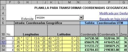
If this is a section of 6 ° longitude by 8 ° latitude, corresponding to zone 16, generating the UTM coordinates is simple and sending it to AutoCAD. Suppose someone goes crazy to think that this mesh can be cut from the map:

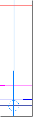
That partition, without calculating the midpoints, the curve would open until it reached the central point where it would generate a difference of 2,318.63 meters of latitude.

When making the following partition, a similar error would be generated, but it will be reduced as follows:
1: 1,000 (6 °): no partition
Split the 1: 500,000 (3 °): 2,318.63
Split the 1: 250,000 (1 ° 30´): 579.76
Split the 1: 100,000 (30´): 129.00
Split the 1: 50,000 (15´): 16.13
 The values are between a partition and the immediate one, so depending on how many times they split, the end result is accumulated, which ends up being a complete disaster if a good cartographer reviews the work.
We also see that if we split the 50,000 sheet to remove the 10,000 mesh we would have an error at the central point of up to 16 meters that for an urban cadastral survey would be extremely serious and worse if it is not uniform because that is the error at the central point .
Although in the 10,000 partition the distance is quite small so the practice of splitting this sheet on the map is very common ... as long as it can be avoided it will be better.
A problem is to want to generate the grid in latitudes and longitudes as we saw in this postFor printing purposes, but the most serious problem is when and reprojection (such as NAD27 to NAD83) with a program made for such purposes, this will generate splice errors that will make topological cleaning torture.