
Enter data with bearings and distances in Microstation
I get the following question:
Hi Greetings, I would like to know how to draw a polygon from directions and distances in MicroStation, and if you can use the Excel Sheet that you provided for AutoCad
Well, in an earlier post we explained How to do it with AutoCAD and an Excel table that facilitates it to be entered in Excel and only copied to AutoCAD.
In the case of Microstation, the case is different. In this case I am going to explain how to enter a traverse using bearings and distances;
1. The format of angular units
 By default comes decimal angles from the east, but if what we want is to enter a polygon as shown in the drawing
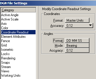
To define the angular format you have to do
Settings / design file / coordinate readout
And here in the "angles" section set the "Bearing" format, with the format degrees, minutes, seconds (DD MM SS). Then it is OK. Be careful, these are properties of the drawing, not a general Microstation configuration.
2. Delete the "save last angle"
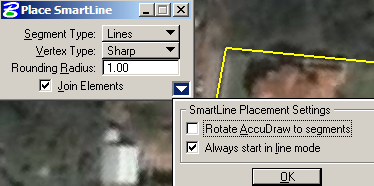
This is a fairly common error, and if it is not configured when creating a line, the system considers the last line as a base angle, as if we were to work by deflections and it is necessary to be right-clicking each line segment .
To avoid the problem, when activating the line command, you have to remove the option "Rotate AccuDraw to segments" as it appears in the following graph.
3. Activating the AccuDraw
Once you start inserting lines, when you place the first point the "Place smart lines" panel appears, to activate the "AccuDraw" panel press the "Toggle AccuDraw" button, if no  being available is activated by right-clicking on that zone and selecting an option to display it.
As you can see, there appears the panel to enter the distance and angle in "Bearing" format. 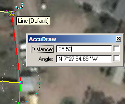 Once entered the data must be entered, and so on until the polygon is completed.
3. Switch between Rectangular and Polar
To change between this option and the one of XY coordinates, the shortcut letters are used:
It means that when the AccuDraw is activated, the blue zone is clicked and any of the "X" or "Y" keys are pressed, the panel changes immediately to be able to enter coordinates.
 To move to distance form, angle any of the "A" or "D" keys is pressed.
4. With Excel?
I do not think it's that difficult, you should only make a table in Excel that converts a box of bearings and distances to xy coordinates, then imports it with Microstation as a txt file ... In the next post we will do it.


Thanks Geofumadas, with this explanation it helps me a lot in my work, you are the best and I want this page to be always well updated …… thank you