
Convert images to vector
Some time ago, the digitizing tables were the output to vectorize printed maps, then came the scanner, although the task not only applies to scanned maps but others that were converted to image or pdf and that we do not have the vector format.
The procedure I'm going to show is using Microstation Descartes, but the same can be done for any other program: AutoDesk Raster Design (Before CAD Overlay), ArcScan, Manifold GIS (Business Tools), I remember that for a long time I did with Corel Draw.
1. The picture
There are some factors that go into making vectoring possible without minor headaches. Among these the image format, a png or tiff will give better results, while a jpg is almost impossible; The resolution to which it was exported also influences, because if it was converted from the printing or export module, it would normally have a scale associated with the paper size, the larger the paper size, a better resolution could be expected or at least better conditions than a simple print screen.
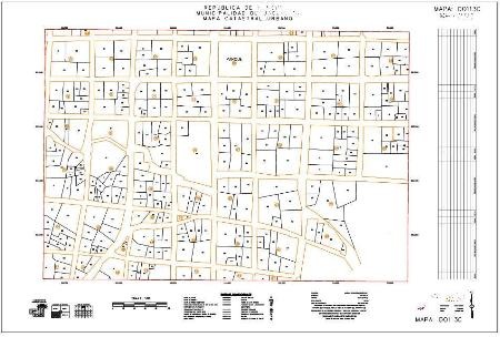
The example I am going to use is a 1: 1,000 cadastral map that was exported from the Microstation printing module, to an 24 "x36" sheet, in tiff format.
2. The georeference
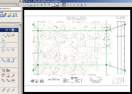
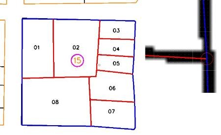
A map like this is easy to georeference because it has coordinates in the margin. I have drawn the points using the command "Place point", And entering the keyin the coordinate in the form "xy = X coordinate, Y coordinate", Those are the blue dots of the bottom image.
Then I have called the reference image, placing it a little outside of those points. Then I have placed the same points in a different color, intersecting with the green lines, always using an exaggerated thickness to make them visible. And finally using "edit, warp" from the raster manager, I have applied the four control points as seen in the figure. You should now be able to vectorize to scale.
Although Microstation V8i supports calling a pdf file as an image and this can be georeferenced with the previous procedure, the vectorization process does not apply because it requires that you have writing rights. It will be necessary to load it, and save it as an image (right button, save as...).
3. The vectorization
 I am using Microstation Descartes V8i. Although this works the same with previous versions.
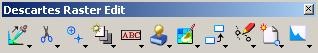
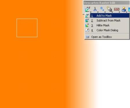
Activate Descartes Tools. 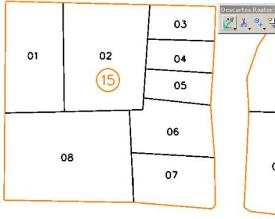 For this we do "tools, raster, raster edit”And that displays a bar that contains the basic tools for image processing.
Let's do the exercise on the 15 apple to explain the scrawl what is there to do:
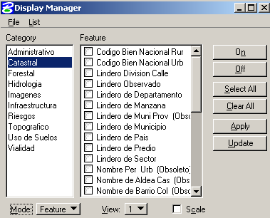
Select the mask. The first icon allows you to create masks, based on criteria, in this case I will use the colors, indicating that I want to add orange to the mask. You have to get closer to the center of the line, and select a box in the area where the color looks flat. To configure the color that you want to display the mask, do with the option “color mask dialog"In my case I have chosen green. It is also possible to create multiple skins and save the configuration in .msk format
Immediately what is selected in the mask changes to the indicated color (green). You can also add more colors to the same mask, or subtract them.
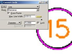 Vectorize circles. We are going to build the circles that are seen in the numbering of blocks, for this it asks us for a radius and then we just have to touch the line of each of the circles. Super simple, I used a magenta color and enough thickness for visual matters. You have to specify a maximum line width, this is done by measuring a distance that exceeds the line width in the image. For better control, it is appropriate to tell it to erase the vectorized image.
The Normalization. To avoid making more vertices because of the Pixilated, a normalization factor is assigned. The example is a non-normalized one, see how the lines are affected by pixelation.
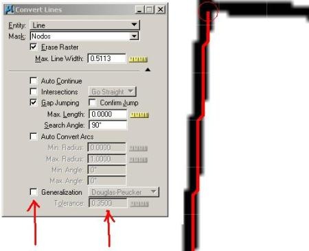
Vectorize boundaries with topology. Now I want to digitize the boundaries, if I made a separate mask for apple boundaries, it would have the problem that they would not have topological cleaning in the internal boundary nodes. To do this, I add orange and black to the mask, then touch the vectors separately. The signal is that they will all be placed in the color of the mask, then only touched using the option "convert lines"
Simple, that's it. See the enlarged detail, that the nodes have been recognized keeping topological coincidence in the vertices, the nodes can be stored as a .nod format file. You can choose the change of color or level when you want, it is what I have done to separate the boundary of the block from the property even working with a single mask.
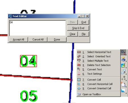
Convert text. For this, there are other tools that allow you to choose horizontal, rotated, multiple text, among others, by applying OCR. Right there it is to convert blocks (cells).
 Other vector options. Once a mask has been applied, the tasks that can be applied include:
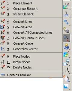
4. Convert lines individually
5. Convert an entire framed area into a frame
6. Convert all connected objects on the map
7. Constructing Contour contours, requires being in an 3D seed file.
8. Build Circles
9. Simplify vectors, this is for line strings that have too many segments
The precision. I have measured the distance from the front of property number 2, and it has given me 28.9611 meters, the original was 29.00, vectoring it on foot would have made the same difference, but slower, with a digitizing table it would have been worse. In this precision, several factors must be considered, such as the quality
d of the scan, if the sheet was not deteriorated, the scale of the map, the quality of the pixelated and especially the georeferenciación of the 2 of this post.
Massive Vectorization.
If you have a two-color image, or you have something in a hurry it is possible to do massive vectorization, although for this you have to have some aspects in mind:
- If the map contains only boundaries, once done standardization tests could be done simply.
- If the map has texts, the ideal is to convert these first, then with the image cleaning tools remove the dirty leftovers
- If it is a color scan, with an acceptable scan, such as a 1: 50,000 cartographic sheet, it is possible to do it by colors, and making masks with useful names (contour lines, buildings, roads, grid, etc.) to be able to apply it in a way uniform to different images.
- When you have continuous sheets, it is preferable to call them both, make possible adjustments by splicing and vectorizing having the different sheets selected.
- It is advisable to do later supervision, especially in the splices and areas of close proximity of lines.


Good thing I hope it works with 8.5, because it would be very important.